Flanged Gate Valve Installation Guide: Bolt Torque Sequence, Gasket Selection, and Leakage Prevention
A flanged gate valve can leak even when the valve itself is correct. Most site problems come from dirty flange faces, the wrong gasket, poor pipe alignment, uneven bolt loading, or rushed pressure testing. A clean installation plan helps prevent those issues before the line goes live.
For cast steel pipeline isolation, buyers can review the PANS wedge gate valve before installation planning. The valve, flange class, gasket type, and test procedure should all match the same service condition.
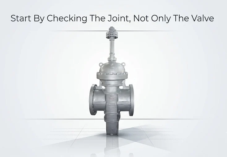
Start By Checking The Joint, Not Only The Valve
Before the valve is lifted into position, confirm the tag number, pressure class, flange standard, body material, and end connection. Also check the bore for debris. Packing material, dust, or loose foreign matter can enter the line during installation if nobody checks it early.
The pipe flanges need the same attention. The valve may be built correctly, but the joint can still fail if the mating flanges do not match. The ASME B16.5 pipe flange standard covers pressure-temperature ratings, dimensions, tolerances, materials, marking, and testing for NPS 1/2 through NPS 24 flanges and fittings.
For long pipeline isolation where low pressure drop matters, the PANS flat gate valve may also be worth comparing. Its product details align with API6D, ASME B16.34, ASME B16.5 flange ends and API598 inspection, which helps buyers connect product choice with site testing needs.
What Should Installers Check Before Placing The Gasket?
A gasket cannot fix a bad flange surface. Before placement, remove old gasket material, oil, rust flakes, paint buildup, and grit from both sealing faces. A small hard particle can hold the gasket open enough to create a leak path.
After cleaning, inspect the raised face or ring groove. Look for scratches, pits, dents, or weld spatter across the sealing area. Damage outside the gasket path may be less serious, but damage across the sealing path should be reviewed before assembly continues.
Bolts and nuts should not be treated as reusable by default. Replace fasteners with damaged threads, heavy corrosion, stretching, or wrong markings. When the site procedure calls for lubrication, apply it consistently to threads and nut-bearing faces. Uneven friction can turn a correct torque value into an uneven bolt load.
How Do You Choose The Right Gasket For A Flanged Gate Valve?
Gasket choice should follow the medium, pressure class, temperature, flange face, and site standard. A compressed fiber gasket may suit some water lines. Flexible graphite may fit higher-temperature service. Spiral wound gaskets are common on many raised-face steel flanges. RTJ gaskets belong with ring-type joint flanges.
The FSA Gasket Handbook explains that gasket material, flange type, surface finish, and service conditions should be reviewed together. That is a practical point because a gasket can fail from chemical attack, over-compression, relaxation, or poor surface contact.
Never reuse the old gasket from a removed flanged gate valve. Once compressed, the gasket has already taken its set. Reusing it may save a small item cost, but it can cause a failed hydrotest or delayed startup.
| Installation Check | What The Crew Should Look For | What Can Go Wrong |
| Flange face | Clean, flat sealing path with no deep damage | Gasket cannot seal evenly |
| Gasket type | Matches medium, face type, and pressure class | Crushing, blowout or relaxation |
| Pipe alignment | Valve fits without forcing the pipe | Uneven gasket stress |
| Fasteners | Correct grade, clean threads and no stretching | Weak or uneven clamp load |
| Torque pattern | Cross-pattern tightening in stages | One side of the gasket overloads |
What Is The Correct Bolt Torque Sequence For A Flanged Gate Valve?
The bolt torque sequence is where many good installations go bad. One common mistake is tightening around the flange in a circle from the start. That pulls the joint unevenly and can crush one side of the gasket before the rest of the flange is seated.
A safer method is staged cross-pattern tightening. Bring all bolts snug first. Then move through the cross pattern in steps, such as 30%, 60%, and 100% of the target torque. After the last cross-pattern pass, some procedures use a final circular check to confirm every bolt reached the required value.
The actual torque value should not be guessed. It depends on bolt size, bolt grade, gasket type, flange class, lubrication, and project procedure. ASME PCC-1 gives guidance for pressure-boundary bolted flange joint assembly and is often used when facilities build flange assembly procedures.
How Can Installers Prevent Leakage During Hydrotest And Startup?
A valve installation guide should not stop at tightening. Before the hydrotest, confirm the valve position required by the test plan. Also check that the flange joints, bonnet joint, and packing area can be seen during inspection.
During filling, follow the site procedure for venting and pressure increase. If the line is filled too quickly, trapped air or sudden pressure change can make inspection harder. When leakage appears, depressurize before correction unless the site safety rule clearly allows another method.
A startup brings a different risk. Hot service can relax the gasket after the first heat cycle. Steam, hot water, and thermal oil lines may need a planned recheck once conditions are safe. That recheck should be part of the commissioning plan, not an emergency reaction.
What Installation Support Can PANS Provide Before Shipment?
Good installation starts during procurement. If the valve, flange standard, gasket, and test requirements are checked together before shipment, the site crew has fewer surprises. PANS can help buyers align flanged gate valve selection with pipe class, end connection, gasket plan, and inspection requirements.
That support is useful when a project includes many sizes or pressure classes. A mixed valve package can create confusion if drawings, flange standards, or gasket notes are unclear. With PANS’ engineering and installation guidance, buyers can reduce common site risks such as wrong gasket selection, forced alignment and unclear pressure-test expectations.
For one-stop sourcing, related pipeline fittings can also be coordinated with the valve order. This makes the installation package easier to check before the crew starts bolting.
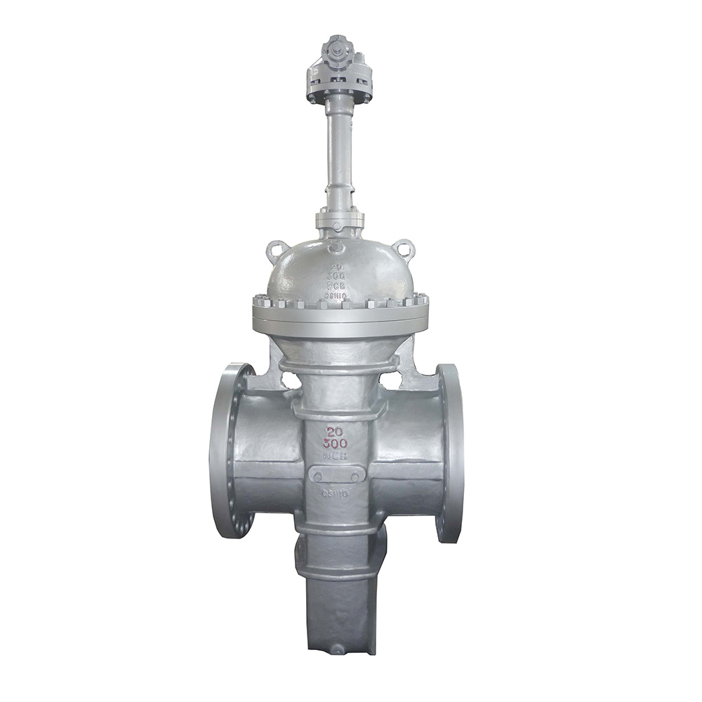
Flat Gate Valve
Design & Manufacture Standard: API 6D / ASME B16.34
Face to Face: ASME B16.10
Field Questions Before A Flanged Gate Valve Goes Live
1. Can A Flanged Gate Valve Be Installed In Any Direction?
Many gate valves are bidirectional, but installers should still check body markings, drawings, and manufacturer instructions. Some project conditions or special designs may require a preferred orientation.
2. Should Bolts Be Tightened In A Circle?
No. Start with a cross-pattern bolt torque sequence and tighten in stages. A circular pattern can load the gasket unevenly if used too early.
3. Why Do Flanged Joints Leak After Installation?
Common causes include dirty flange faces, wrong gasket material, poor alignment, damaged bolts, uneven torque, rushed filling, or pressure testing before inspection is complete.
Build The Installation Around Leak Prevention
A flanged gate valve is only as dependable as the joint around it. Clean flange faces, correct gasket selection, proper alignment, and staged bolt loading all protect the seal before pressure reaches the line.
PANS helps buyers reduce leakage risk by matching the gate valve, flange standard, and installation support to the project before shipment. When the product choice and field procedure agree, the crew spends less time fixing leaks and more time moving the pipeline toward safe operation.
Search
Categories
Tags
Product
- Ball Valve
- Floating Ball Valve
- Fully Welded Ball Valve
- Trunnion Ball Valve
- Butterfly Valve
- Full Metal-Seated Bi-Directional Butterfly Valve
- High Performance Butterfly Valve
- Three-Eccentric Metal Hard Seal Butterfly Valve
- Check Valve
- Cast Lift Check Valve
- Cast Swing Check Valve
- Wafer Type Check Valve
- DIN Valve
- DIN Bellow Sealed Globe Valve
- DIN Globe Valve
- DIN Rising Stem Gate Valve
- DIN Swing Check Valve
- Forge Valve
- Forged Check Valve
- Forged Floating Ball Valve
- Forged Gate Valve
- Forged Globe Valve
- Gate Valve
- Bellow Sealed Gate Valve
- Flat Gate Valve
- Wedge Gate Valve
- Globe Valve
- Cast Globe Valve
- Plug Valve
- Eccentricity Plug Valve
- Inverted Pressure Balance Lubricated Plug Valve
- Orbit Plug Valve
- Sleeve Type Plug Valve
- Slurry Valve
- Slurry Valve
- Strainer


