How to Size a Valve: Cv, Kv & Step-by-Step Calculation
Valve sizing comes down to one number: Cv. Or Kv if you are working in metric. Selecting an appropriate Cv or Kv helps achieve the required capacity, but control performance across the operating range also depends on valve characteristics, rangeability, actuator and positioner performance, and the installed system. Get it wrong, and you end up with a valve that either chokes the system or sits nearly closed all day, destroying its own seat. PANS Valve manufactures ball, gate, globo, butterfly, and check valves across a full range of pressure classes and sizes, with technical support for valve selection and sizing across oil and gas, petrochemical, power-generation, and water-system applications.
Why Does Proper Valve Sizing Matter?
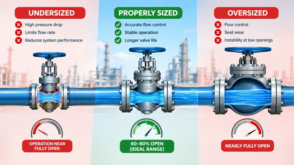
Oversized. Undersized. Both are problems, just different ones.
An oversized valve operates near closed at normal flow. Poor control. Seat wear. Instability at low openings. An undersized valve restricts the system, increases pressure drop, and prevents the plant from reaching required flow rates. Neither condition is acceptable in a process that depends on reliable flow control.
A properly sized control valve should operate within a stable and controllable travel range at minimum, normal, and maximum conditions, with adequate margin at both ends of travel. The preferred travel range depends on the valve design and project criteria. That is where stable, controllable operation lives. Outside that range, performance degrades fast.
What Are Cv and Kv?
Cv. Simple definition. The number of US gallons per minute of water at 60°F that flows through a valve with exactly 1 psi pressure drop across it. That is it. One number that tells you the flow capacity of any valve regardless of manufacturer.
Kv is the metric version. Cubic meters per hour of water at 1 bar pressure drop. Same concept, different units. Conversion between the two: Cv = 1.156 × Kv. The valve Cv calculation formula for liquids is:
Cv = Q × √(SG / ΔP)
Q is flow rate in GPM. SG is specific gravity relative to water. ΔP is pressure drop in psi. Straightforward. The complexity comes in how you define those inputs correctly.
How Do You Size a Valve for Liquid Service?
How to size a valve for liquids. Four steps. No shortcuts.
Step 1: Define operating conditions. Normal flow, minimum flow, maximum flow. Inlet and outlet pressures at each point. Calculate ΔP for each condition. You need all three, not just the design point.
Step 2: Calculate required Cv. Calculate the required Cv at minimum, normal, and maximum operating conditions. Select the valve by comparing each required Cv with the manufacturer’s Cv-versus-travel curve while preserving a suitable travel margin at maximum flow.
Step 3: Select the valve. Find a valve with published Cv at or above the calculated value. Confirm that normal flow occurs within the project’s preferred control range and that sufficient additional travel remains for the maximum-flow condition. Not near closed. Not wide open.
Step 4: Check cavitation. Evaluate cavitation and liquid choked flow using absolute inlet pressure, vapor pressure, critical pressure, the valve pressure-recovery factor FL, and the applicable IEC/ISA equations. Outlet pressure above vapor pressure alone does not rule out cavitation. Cavitation destroys trim, especially in globe valves with high pressure drop across the seat.
What Are the Basics of Gas and Steam Sizing?
Different fluid. Different approach. The table below summarizes what changes across fluid types for valve sizing.
| Fluid | Primary Concern | Key Variable | Main Risk |
| Liquids | Constant density | Specific gravity, vapor pressure | Cavitation, flashing |
| Gases | Compressibility | Critical pressure ratio | Choked flow at sonic velocity |
| Vapor | Phase state | Superheat or saturation condition | Erosion, wet steam |
Gas sizing gets more complex because the fluid compresses. Choked flow kicks in when pressure drop hits around 50 percent of absolute inlet pressure. Once gas flow is choked at a given valve travel and upstream condition, further reduction of downstream pressure does not produce the normal increase in mass flow. Increasing valve travel can still increase effective Cv and flow capacity. Steam adds another layer. Saturated or superheated. The answer to that question changes the entire calculation approach.
What Are the Key Sizing Rules of Thumb?
Four rules. Apply them every time.
Normal operating flow should land the valve at 60 to 80 percent open. Maximum flow should not push past 80 percent. Minimum controllable flow should not require less than 20 percent opening. Rangeability, the ratio of maximum to minimum controllable flow, must be confirmed against the valve’s published specification. Violate any of these and the valve either loses control authority or wears out prematurely at one end of its travel.
What Are the Most Common Valve Sizing Mistakes?
Five. All avoidable.
Oversizing. Too much Cv. Valve hunts near closed. Operating continuously near the seat may increase instability, velocity, and wear, potentially shortening trim and seat life.
Undersizing. Not enough Cv. System never reaches design flow. Pressure drop kills performance.
Ignoring cavitation. No cavitation check during sizing. Trim erodes. Noise. Vibration. Expensive repair.
Mixing units. One input in metric, one in imperial. Calculation is off by a factor of two or more. Wrong valve gets ordered.
Ignoring turndown. Sized only for maximum flow. Minimum flow condition makes the valve uncontrollable. Startup and low-load operation become problems.
Step-by-Step Worked Example
Water service. Here is the full calculation.
Given: Flow rate 100 GPM. Specific gravity 1.0. Inlet pressure 50 psi. Outlet pressure 35 psi.
Step 1: ΔP = 50 – 35 = 15 psi.
Step 2: Valve Cv calculation. Cv = 100 × √(1.0 / 15) = 100 × 0.258 = 25.8. Select a valve with Cv of at least 26.
Step 3: Confirm the selected valve delivers 100 GPM at 60 to 80 percent open under normal operating conditions. If it only reaches 100 GPM near fully open, the valve is undersized for good control.
Step 4: Cavitation check. Outlet pressure is 35 psi. Verify this stays above the vapor pressure of water at operating temperature. At 60°F, the vapor pressure of water is approximately 0.26 psi. 35 psi is well above that. No cavitation risk in this example.
What Tools and Calculators Are Available for Valve Sizing?
Several valve sizing calculator tools exist. Online Cv calculators from major valve manufacturers accept flow rate, pressure drop, specific gravity, and temperature, then return required Cv with cavitation and choked flow warnings. ISA formal sizing equations cover liquid, gas, and steam in detail. Specialized sizing software calculates Reynolds number, cavitation index, and critical pressure ratio automatically and flags problems in the output. Most serious sizing programs will also recommend alternate sizing routines when laminar flow conditions are detected.
For PANS Valve product selection and sizing support, contact PANS Valve for technical assistance and project-specific valve sizing guidance across ball, puerta, globe, butterfly, and controlador de el volumen applications.
Preguntas frecuentes
What are standard valve sizes?
Available nominal sizes and pressure classes depend on the valve type, applicable product and end-connection standards, material, and manufacturer’s qualified design range. Confirm the permitted size–class combination for the specific valve. The correct size for a specific application is determined by Cv calculation, not pipe diameter alone.
What are the rules of thumb for valve sizing?
Normal flow should produce 60 to 80 percent valve opening. Maximum flow should not exceed 80 percent open. Minimum flow should not require less than 20 percent opening. These ranges ensure stable control authority across the full operating range of the system.
How do you size a pressure relief valve?
Pressure relief valve sizing follows different methods from control valve sizing. It is based on required relieving capacity at set pressure, fluid type, and allowable overpressure. API 520 and API 521 govern pressure relief valve sizing for oil and gas and petrochemical applications.
What is the difference between Cv and Kv?
Cv is the imperial flow coefficient measuring US gallons per minute of water at 1 psi pressure drop. Kv is the metric equivalent measuring cubic meters per hour at 1 bar pressure drop. The conversion factor is Cv = 1.156 × Kv.
Buscar
Categorías
Etiquetas
Producto
- Válvula de bola
- Válvula de bola flotante
- Válvula de bola completamente soldada
- Válvula de bola de muñón
- Válvula de mariposa
- Válvula de mariposa bidireccional con asiento totalmente metálico
- Válvula de mariposa de alto rendimiento
- Válvula de mariposa con sello rígido de metal y tres excéntricas
- La válvula de retención
- Válvula de retención de elevación fundida
- Válvula de retención oscilante fundida
- Válvula de retención tipo oblea
- Válvula DIN
- Válvula de globo sellada con fuelle DIN
- Válvula de globo DIN
- Válvula de compuerta de vástago ascendente DIN
- Válvula de retención oscilante DIN
- Válvula de forja
- Válvula de retención forjada
- Válvula de bola flotante forjada
- Válvula de compuerta forjada
- Válvula de globo forjada
- Válvula de compuerta
- Válvula de compuerta sellada con fuelle
- Válvula de compuerta plana
- Válvula de compuerta de cuña
- Válvula de globo
- Válvula de globo fundida
- Válvula de tapón
- Válvula de tapón de excentricidad
- Válvula de tapón lubricada con equilibrio de presión invertida
- Válvula de tapón orbital
- Válvula de tapón tipo manguito
- Válvula de lodo
- Válvula de lodo
- Colador


